
An automated anisotropic mesh adaptation technique used for the electromagnetic processing of materials
However, harnessing the full potential of electromagnetic-based processes requires sophisticated modelling and simulation tools that can accurately capture the complex physics involved. The precise adaptation of the mesh is instrumental in achieving not only accuracy in simulations but also minimizing computational cost and reducing CPU time. Understanding the significance of this aspect, adaptative mesh techniques within Forge® have been developed.
Adaptative remeshing plays a crucial role in the accuracy and efficiency of simulations. Having a well-distributed mesh that automatically adapts to the requirements of the physical phenomena is essential for achieving reliable and robust results. Building upon the work presented in error estimators, we have developed tools that enable automatic mesh adaptation based on error estimation procedures. Several manufacturing examples are shown demonstrating their effectiveness in providing accurate simulations.
Examples: Induction Heating for surface hardening
Induction hardening is a crucial process in industrial manufacturing, aimed at enhancing the hardness and durability of vital components. To achieve optimal performance and efficiency in this demanding application, precision and accuracy are of utmost importance. This is where our cutting-edge development in advanced mesh adaptation techniques comes into play. We investigate the induction hardening process used in the manufacturing of a wheel bearing that has been carried out in collaboration with NTN-SNR. The setup consists on two inductors and field concentrators strategically placed in the area where heat treatment is required to create a concentrated magnetic field towards the part. To optimize the computational efficiency, we have considered the geometry's axial symmetry and only simulated a portion of it as can be seen in the Fig. 1
We have extensively tested and compared our innovative approach with a fully isotropic mesh structure, ensuring its effectiveness.
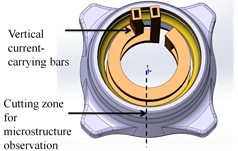
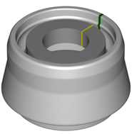
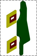
Fig. 1 Wheel bearing application
The magnetic field is visualized to observe its behavior in the region between the inductors and the part. This visualization allows us to gain insights into the interaction and distribution of the magnetic field in this critical area. By examining the magnetic field, we can better understand its impact on the electromagnetic process.
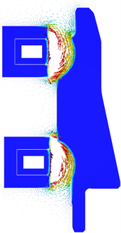
Fig. 2 Magnetic field (A/m) distribution over the wheel bearing
The automatic remeshing procedure is expected to adapt the mesh size according to the regions where the magnetic field acts strongly, including the regions influenced by the current concentrators. The simulation results will provide insights into the temperature distribution within the part during the induction heating process, enabling us to optimize the process for improved efficiency and reduced cost.
The distribution of the initial mesh can be observed in Fig. 3, where each part is highlighted for easy visualization of the mesh distribution across the geometries and the surrounding air.

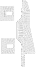
Fig. 3 Mesh distribution of the geometries and the surrounding air.
The new mesh is computed using the metric tensor obtained from the anisotropic mesh adaptation procedure. As expected, the adapted mesh distribution is shown in Fig. 4, where the mesh is refined around the critical areas between the part and the inductors where the magnetic field acts strongly, the surrounding air is also adapted following the magnetic field. This demonstrates the effectiveness of the proposed automatic remeshing procedure in adapting the mesh size to accurately capturing the electromagnetic phenomena.
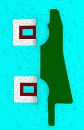
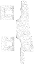
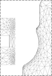
Fig. 4 adapted Mesh distribution of the geometries and the surrounding air.
The performance of the original and adapted meshes were compared to quantify the error and CPU time required for a complete simulation of the hardening process. The original mesh had 100k degrees of freedom, while the adapted mesh had only 26k degrees of freedom. Resulting in a significant reduction in computational cost. It is worth noting that the adapted mesh resulted in a lower error over the simulation compared to the original one, as shown in Fig. 5.
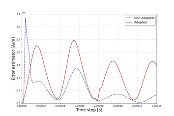
Fig. 5 Error estimator comparison over two electromagnetic periods
The CPU time with the adapted mesh took only 6 minutes compared to 25 minutes for the original mesh. This resulted in a significant reduction in time required for the electromagnetic solution.
Finally, to compare the temperature distribution of the original and adapted mesh, the results are shown at the end of the computation. Fig. 6 illustrates the temperature distribution for both cases, where it is evident that both meshes have a similar temperature profile. The results demonstrate that the proposed anisotropic mesh adaptation procedure can significantly reduce computational cost while maintaining high accuracy in electromagnetic simulations.


Fig. 6 Temperature (°C) distribution on the part: (a) adapted mesh, (b) original mesh.
Magnetic Pulse Forming
The magnetic pulse forming (MPF) technology or electromagnetic forming (EMF) consists in deforming metallic components through the application of an intense electromagnetic pulse. This process enters in the category of high-speed forming processes because of the range of strain rates that are usually attained, ranging from 10^3 s^(-1) to 10^4 s^(-1)..In the following example, a ring expansion case typically used for plasticity characterization under high-speed loading of this process is tested:
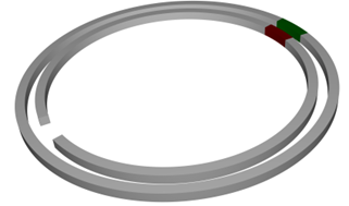
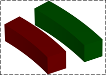
Fig. 7 Ring and symmetry used to perform the simulation (dark red: inductor, green: workpiece).
This case study allows us to evaluate the effectiveness of our approach in capturing the intricate electromagnetic behaviour and adaptively refining the mesh for accurate simulations in challenging industrial applications.
![]()
![]()
Fig. 8 Magnetic field [] and Current density [] distribution over the inductor and workpiece
The initial mesh as well as the adapted mesh are presented. The adapted mesh is generated in order to follow the electromagnetic behaviour displayed above.
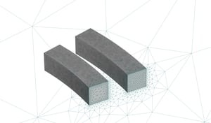
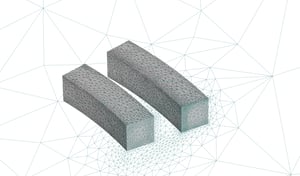
Fig. 9 Mesh before and after adaptation
The results clearly demonstrate the effectiveness of the put methodology in capturing the underlying physical phenomenon and adapting the mesh to minimize the overall simulation error. The adaptation of the mesh can be observed as it closely follows the current density directions, achieving a substantial reduction in the number of DoF
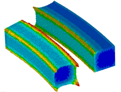
The temperature distribution over the ring is depicted in the following image, demonstrates a good agreement between the adapted mesh employed in the electromagnetic solver and the temperature evolution.
![]()
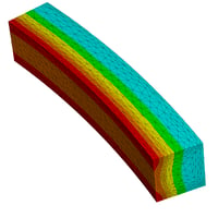
Fig. 10 Temperature (°C) distribution of the ring
Electromagnetic Stirring
These développements are also being couples with THERCAST® which also encompasses the simulation of electromagnetic stirring, a prominent process extensively employed in the materials forming industry. It consists of using the time-varying electromagnetic field to control the fluid flow between the liquid steel and the stirrer without any physical contact. It enables disrupting the molten metal’s fluid flow by means of the Lorentz force provided by a linear induction motor allowing a more homogeneous solidification. We showcase a case where strategically placed inductors are employed to achieve the homogenization of molten metal in a casting process. The careful positioning of these inductors plays a crucial role in ensuring the uniformity and consistency of the metal throughout the casting operation. By utilizing electromagnetic forces generated by the inductors, the molten metal is effectively manipulated, resulting in improved casting quality and reduced defects.
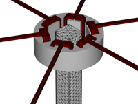
Fig. 11 Electromagnetic stirring case
In this case, we present the visualization of the magnetic field lines induced by the inductor, along with the distribution of eddy currents within the molten metal.
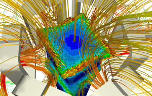
Fig. 12 magnetic lines and current density induced on the part.
After the mesh adaptation, the resulting mesh and the distribution of errors are displayed in the following image.
Adapted mesh Error distribution
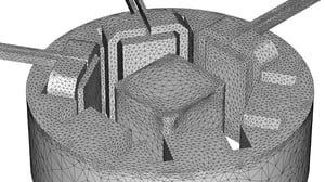
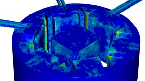
Fig. 13 Electromagnetic stirring mesh and error distribution results
In this complex geometric configuration, our automatic mesh adaptation procedure demonstrates its effectiveness in significantly reducing errors throughout the part and inductors, resulting in a highly accurate representation of the physical phenomenon. Notably, our procedure does not require a geometry with a precise initial mesh, as it dynamically adjusts the mesh to align with the physics of the system. This adaptive approach ensures optimal mesh distribution, enabling precise tracking of the electromagnetic effects and enhancing the overall simulation accuracy.
The next step will consist of a full integration of this new strategy in the fully coupled framework of FORGE®/THERCAST® such that all these different processes can be simulated in an even more seamless manner.
Papers
Error estimation: A-Posteriori Error Estimator for Finite Element Simulation of Electromagnetic Material Processing
Anisotropic Mesh Adaptation (draft version): Anisotropic Mesh Adaptation Based on Error Estimation for 3D Finite Element Simulation of Electromagnetic Material Processing