Simulation of mechanical joining with COLDFORM®
 The mechanical joining process offers several advantages compared to other joining techniques (adhesive joining or welding). It can be used for weldable and non-weldable materials, aluminium and magnesium alloys, and brings benefits to lightweight industry. There is no chemical interaction during this process (no change in chemical composition or microstructure) and its efficiency depends only on the materials, and not on atomic or molecular bonds.
When using mechanical joining, dissimilar materials can be assembled (metal-glass or metal-plastics) and dismantled under certain conditions. The drawbacks of this process are the possibility of fatigue phenomena or corrosion at the fastening point, as well as self-loosening.

- Ensure process feasibility by checking every step of the ‘set-up’ phase
- Check the influence of process parameters (coating, etc.)
- Master dimensional control and fastener properties
- Take advantage of the initial conditions due to the manufacturing process (thermo-mechanical history of the material)
- Test the behaviour of the fastening solution under in-service conditions
- Predict fastening performances and lifetime

Competitive features of COLDFORM® for mechanical joining
- Multi-body contact is modeled using a Master/Master or Master/Slave algorithm in 2D and Master/Slave algorithm in 3D, which facilitates mechanical resolution of coupling between the bodies.
 Latham Cockroft criterion (damage) on a self-piercing riveting simulation
- During blind riveting applications: self-contact areas appear where the metal flows over itself.
- Your own material file can be created using the “Cold rheology generation tool”, or other material sources of data such as a JMatPro, Total Materia or FPD database.
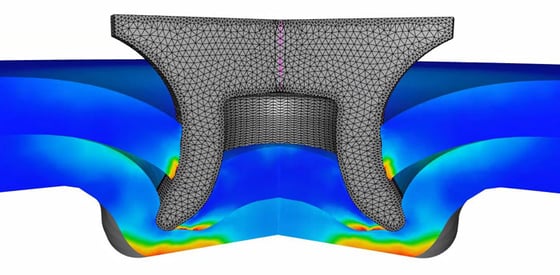
- Self-adaptive remeshing is performed during the self-piercing riveting simulations on the boundary profiles.
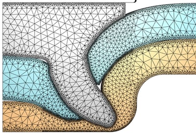 Self-adaptive remeshing
- Several damage & rupture criteria are developed and used as user routines, including Latham & Cockroft, Oyane, Ryce&Tracey, Chaboche-Lemaitre, etc. These damage criteria can be used in self-piercing riveting simulations.
- Automatic element deletion is performed when the trigger value for damage criteria is reached.
Case studies of clinching and riveting processes
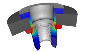
Von Mises stress on clinching process
The clinching setup is axisymmetric – a 2D configuration is used in this case study.
Distribution of effective strain during the clinching process
To correctly estimate the final stress state of the assembly, an elastic unload simulation needs to be performed (figure 1). It is possible to use the “displacement view” feature available in the post-processor to magnify the display of the displacement field (figure 2).
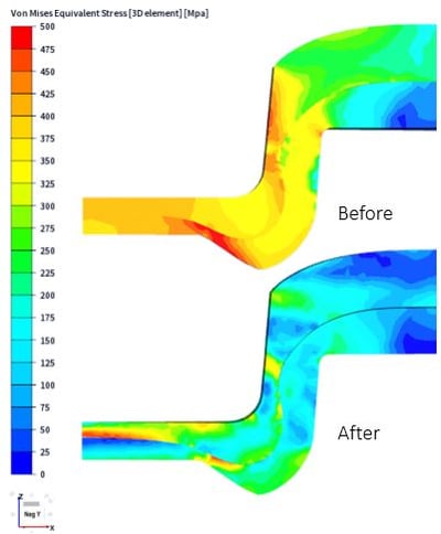
1) Distribution of von Mises stress before and after elastic unload
2) Displacement results during elastic unload magnified by 5
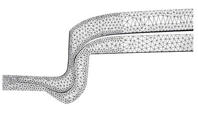
A simple tensile test can be modeled to observe stress loading. In this test, two dies are defined, one on the upper side, which will pull the upper sheet, and the other on the lower side, which will maintain the extremity of the lower sheet in position. The sticking behavior between dies and parts are ensured using the “bilateral sticking” friction file.
Distribution of von Mises stress during the tensile test
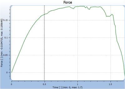
Disassembly force curve during the tensile test
Equivalent strain on self-piercing riveting process
This paragraph is dedicated to the results analysis for a self-piercing riveting case. The video presents the variation in the equivalent strain set from 0 to 3. At the end of the self-piercing riveting process, the release of stress due to the elastic unload is computed in the three main parts.
Variation in the equivalent strain during self-piercing riveting
The figure below presents the distribution of Von Mises stress before and after elastic unload. A high stress spot can still be seen in the rivet.
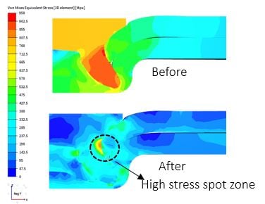
An analysis of shearing due to disassembly is also feasible with COLDFORM®. It is possible to plot and compute the disassembly force needed and the stress results as shown below.
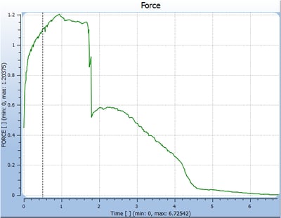
Disassembly force during the process
Need a quote or more info about COLDFORM®?