
Among the key techniques available to forging designers, the so- called ‘automatic optimization’ is one of the most attractive. The term ‘optimization’ encompasses many aspects and obviously every forging company tries to optimize its daily production. In other words, optimization applied to a forging process aims at reducing production costs and improving the quality of the manufactured part. This is where numerical simulation with our FORGE® and COLDFORM® and SIMHEAT® software comes into play.
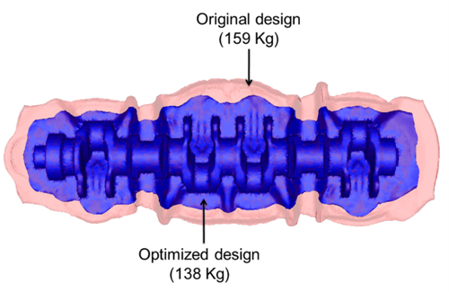
FORGE® simulation without optimization in red, and with optimization in blue

What is automatic optimization in process simulation?
In the field of Finite Element Modeling, ‘optimization’ or ‘optimizing’ means running a series of simulations to identify the ideal process conditions giving the best final result.
Optimization follows a number of set parameters:
- Objective (situation to be studied): billet weight, die wear or die stress, tonnage, difference with experimental plots, etc. The objective can be to minimize or to maximize.
- Process conditions: billet size or position, lubricant, temperature, die geometry, etc.
- Constraints to respect (additional mandatory condition): complete filling of the die cavity, no folds or laps, prescribed scalar value, prescribed force or torque value, etc.).
How does it work?
Automatic Optimization is based on MAES methods (Metamodel-Assisted Evolution Strategies) proposed by Emmerich et al. [1], which has shown its efficiency and robustness in several complex metal forming applications [2,3].
Each simulation uses a set of process parameters (diameter and length) and is referred to as an ‘individual’. Each ‘generation’ includes several individuals. Good individuals (in green) match the objective and respect the constraints. Poor individuals (in orange) do not respect the constraints. The next generation is automatically based on the best current individuals.
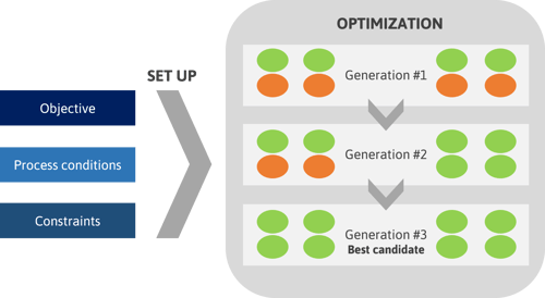
The algorithm loops until the given number of generations has been reached. At each generation, a new population of individuals is created. A cost-function is used to rank each individual and designate the ‘best candidate’.
Defining a Design of Experiment (DOE), the user indicates to the system a selection of values (process conditions) to be tested. Combining Automatic Optimization based on Metal Model Design with the DOE is a good technique to find the solution somewhere near one of the tested values.
PARALLEL CALCULATIONS
The algorithm handles two levels of parallelization: the parallelization of the finite element software itself, which is here automatically managed by the FORGE® software, and the parallelization of the optimization algorithm. As the exact number of function evaluations is a priori known for each algorithm iteration, these can easily be carried out in parallel. The combination of these two parallelization strategies significantly reduces the computational cost on a cluster of several processors.
Automatic optimization for metal forming processes
Thanks to the optimization module included in the FORGE® and COLDFORM® software, forging designers benefit from a solid and reliable solution for hot forging and cold forming simulations. This module offers a wide range of optimizations including:
- Achieve savings on raw materials
- Reduce your energy consumption
- Find the optimal design of your parts
- Guarantee total die filling
- Avoid defects (folds, cracks, etc.)
- Optimize tooling geometry
- Increase die life
- Minimize the number of stages in your forming sequence
- Control metallurgical properties
- Reduce the amount of flash in your closed-die forging
- Determine ideal rolled preforms
- Identify heat transfer coefficient
Compatibility with CAD software
Automatic optimization is 100% compatible with conventional CAD systems (Creo Parametric, SolidWorks, Catia, Siemens NX) and parallel computing. You can be even more efficient by launching your optimization on multiple cores and taking advantage of FORGE®’s efficiency in highly parallel computing.
Inverse analysis
It’s usual to have unknown parameters when modeling a forming process. Automatic optimization can be used to solve many inverse analysis problems and to characterize these parameters. For example:
- Characterization of material rheological and tribological parameters
- Identification of friction or heat transfer coefficients
- Identification of the material anisotropic constitutive parameters that allow matching with the final shape of the component after stamping

Automatic optimization case studies
Optimize the dimensions of a camshaft and make material savings
Challenge: How can I optimize the closed-die forging of an automotive camshaft? How do I reduce the amount of flash? How much raw material can I save?
Solution: Using FORGE® automatic optimization module to find the optimal dimensions of the preform.
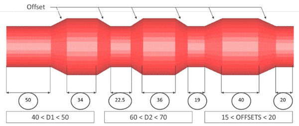
A range of acceptable values is defined for each parameter.
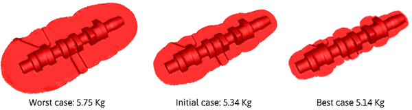
The initial case weighs 5.34 kg. The module calculates the worst case (with the most flash) at 5.75 kg. The best case, with the least flash, is calculated at 5.14 kg. This best case allows a saving of 200 g per part, almost 4% of the initial weight.
Benefits and ROI
ROI estimation:
- With a steel price of ~450 € per ton
- Savings: 9 cents per part => 900 € per batch of 10,000 parts
- Easy to apply within the same product family
The preform volume reduction enables additional savings
- Tonnage reduction from 2000 to 1200 tons
- Increase in press and die life
- Gas savings by reducing heating time in furnace
- Replicate the experience on other product family
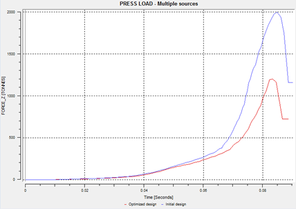
Press load required with the initial design (in blue) and with the optimized design (in red)
Optimize the forming sequence and reduce energy consumption
Challenge: How do I adapt the forming process from 5 to 4 stations? What should be the optimum tooling design for the new intermediate stage?
Solution: Delete the 4th and 5th stations and create a new one. By connecting COLDFORM® with a CAD system, identify the die geometries of the new station assuming a minimal energy consumption with the guarantee of correct filling and no folds.
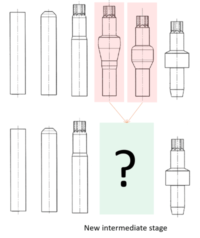
Top: Current forging sequence, Bottom: Desired forging sequence

This case study is conducted in collaboration with SFS Intec. The design parameters are defined on the SolidWorks CAD software and variations are set on the top angle and the diameter of the lower die.
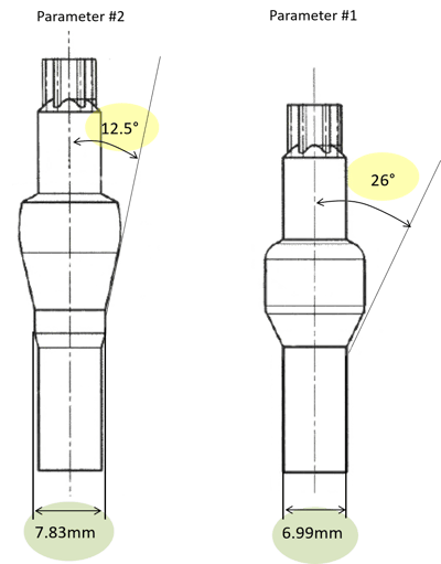
The optimization engine loops with the CAD via a dedicated script procedure. New die designs are automatically imported from the CAD software into the optimization loop at each simulation. The best solution is given for an angle of 13.31° and a diameter of approximately 7.1mm. The two intermediate stations can be replaced with the new intermediate station and the part is successfully manufactured.
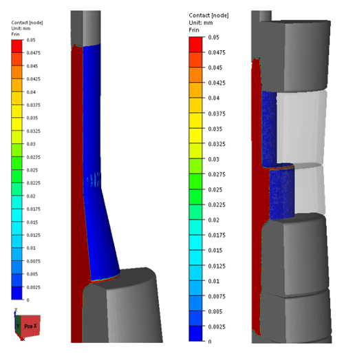
New intermediate station (left) and last station (right)
Benefits and ROI:
- With fewer operations: reduction of total die cost and reduction of total time for die change
- Easy to manage the pool of presses and quote new jobs for the most suitable production line

[1] M. Emmerich, A. Giotis, M Ozdemir, T. Bäck, K. Giannakoglou, Metamodel-assisted evolution strategies. In: Proceedings of the International Conference on Parallel Problem Solving from Natu re, 2002
[2] L. Fourment, T. T. Do, A. Habbal, M. Bouzaïane, Gradient, non-gradient and hybrid algorithms for optimizing 2D and 3D forging sequences, in: D. Banabic Eds. 8th International ESAFORM Conference on Material Forming 2005.
[3] M.H.A. Bonte, L. Fourment, T.T. Do, A.H. Van Den Boogaard, J. Huétink, Optimization of metal forming processes using Finite Element simulations, Structural and Multidisciplinary Optimization