
Numerical simulation of cutting processes represents a major challenge in the field of metal forming. Recent work by our Development team has enabled us to improve the FORGE® model for modeling cracks resulting from this process.

PREDICTING CRACKS CAUSED BY DUCTILE DAMAGE
 There are two main cases for which it is necessary to control damage during the manufacture of a part:
- Cutting: here, the damage is deliberately triggered to cut a geometric shape by tearing a section of material in a controlled manner. Nevertheless, the path of the generated crack and the quality of the surface of this crack are difficult to control.
- Plastic forming: most often, it is desirable to form a part with large plastic deformations while avoiding the appearance of cracks (superficial or internal). Parameters such as the temperature of the billet or of the tools, the choice of lubricants or even the strain rate, can nevertheless induce the appearance of cracks which are, in this case, considered as defects. Manufacturers therefore attempt to predict those conditions under which these defects will appear and in what area of the part.
At this point, numerical simulation is very useful. The appearance and propagation of cracks can be modeled, making it possible to guarantee the quality and safety of final parts. As this phenomenon is relatively complex to simulate, Transvalor has launched a development project to improve the FORGE® model. More information >
FORGE® MODEL IMPROVEMENT WORK
Thanks to the work carried out, a new strategy for inserting real cracks, in 3D mode, into a parallel frame has been implemented in FORGE®. The cutting process simulations thus become more predictive and computation times are reduced.
The latest developments achieved in the context of R&D collaboration with Faurecia Automotive Seating have demonstrated the use of the proposed methodology on a multi-material part, as illustrated in the example below.
Simulation of the initiation and propagation of real cracks during mechanical strength tests on multi-material parts
Figure 1 shows the tooth of an automotive seat system made of two materials: a ductile core (in red) and a low-ductility carbonitride layer (in blue).
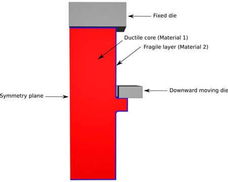
Figure 1: Geometry and boundary conditions of a tooth in the automotive seat system composed of two materials
The initiation and propagation of a real crack with 4 deformation states until the final fracture can be observed in figure 2. The real crack follows a regularized damage field known as “Phase field” which varies between 0 (no crack) and 1 (initiation of a crack). Learn more about the Phase-Field >
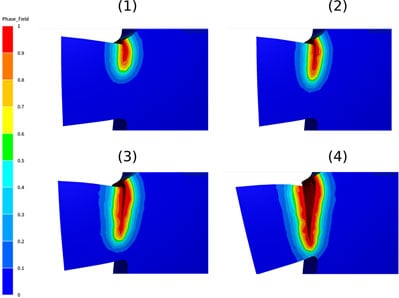 Figure 2: Simulation of crack initiation and propagation during cutting
As shown in figure 3, the surface condition as well as the failure path are very clean and especially less dependent on the mesh used to discretize the geometry than with the kill-element method.
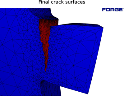
Figure 3: Final crack surface
Cracking is computed in parallel on 6 cores by relying on two techniques: a new local element cutting strategy and adaptive remeshing. The computation starts with a mesh size of 0.25 mm, gradually decreasing to 0.15 mm around the damaged area. The computation time is less than 10 minutes thanks to the fact that the algorithm is based on local remeshing operations (only on damaged areas), which serves to optimize the computation time.
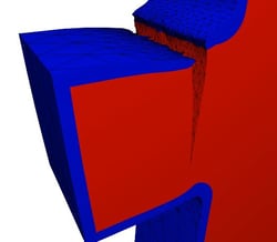
Figure 4, 5 and 6 show the final rupture with the indices of the two materials as well as the parallel partitions.
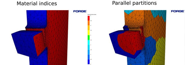
Figure 4: Final part rupture with the indices of the two materials (on the left) and with the parallel partitions (on the right)
Figure 5: Final part rupture with the indices of the two materials
Figure 6: Final part rupture with Phase-field
INDUSTRIALIZATION OF DEVELOPMENTS
![]()
These developments will be integrated in Beta mode in the next version of the FORGE® software. A new damage model based on the “Phase-Field” method will be made available. The next release will allow the use of all the phenomenological models already existing in FORGE®, such as Cockroft-Latham, Lemaître and others, combined with element cutting using the “Phase-field” as a “non-local" damage variable.