
Introduction
Macrosegregation refers to large-scale chemical variations that occur during solidification, caused by uneven displacement and localized accumulation of alloying elements. At the local scale, microsegregation develops within dendrites or between primary cells. In contrast, macrosegregation affects entire volumes of the ingot, causing significant heterogeneities that compromise its metallurgical and mechanical performance. This represents an important industrial challenge, as local variations in carbon or critical alloying elements can degrade the final quality1,2. This phenomenon is particularly pronounced during ingot casting, since large dimensions and complex thermal gradients promote convective movements and solute redistribution3.
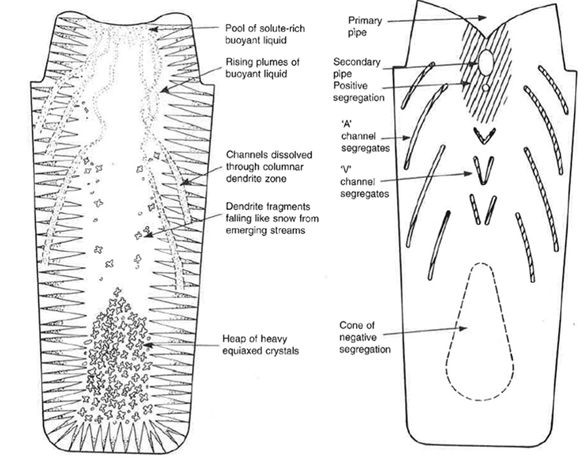
Figure 1 below illustrates the main physical mechanisms involved during the solidification of an ingot. The density difference between solute-enriched and solute-depleted liquid generates upward movements that form channels in the columnar dendritic zone. Dendrite fragments detach, sediment and accumulate as denser equiaxed crystals at the bottom of the ingot. These transfers induce a heterogeneous distribution of the solute, with regions of positive segregation (pipes and channels) and a central zone of negative segregation4,5.
(a) (b)
Figure 1: Schematic illustration of the mechanisms of macrosegregation formation during the solidification of an ingot4. (a) Circulation of solute-enriched liquid, dissolution of channels in the columnar dendritic zone, and formation of equiaxed crystals. (b) Typical distribution of positive segregation zones (primary and secondary pipes, « A » and « V » channels) and the negative segregation zone (central cone).
To anticipate and limit these segregation phenomena, the modeling of ingot solidification relies on finite element models aimed at reproducing the main coupled physical mechanisms. These include notably thermosolutal convection induced by temperature and solute concentration gradients3,6–10, solidification shrinkage3,10, equiaxed grain sedimentation9,11, and deformation of the mushy zone3.
However, the complete and predictive modeling of all these coupled phenomena remains a major challenge, particularly for complex industrial configurations. The THERCAST® software, originating from research conducted at the Centre for Material Forming (CEMEF-MINES Paris PSL), seeks to address this challenge by progressively integrating these effects within a coherent and adaptable simulation framework.
In a previous study, the thermosolutal macrosegregation model was validated by incorporating an analytical calculation of the heat capacity Cp, applied to a well-documented binary system (Hebditch and Hunt12). This validation laid a robust reference groundwork for the development of more complex models that better represent industrial conditions. In continuation of this study, the present article proposes to enhance the previous model by extending the analytical calculation of Cp to multi-binary alloys.
Enhancement of heat capacity calculation in the case of a multi-component alloy
The model of macrosegregation induced by thermosolutal convection is based on several simplifying assumptions: solidification is assumed to be purely columnar, without the formation of equiaxed grains, and the solid is considered fixed and rigid, with no consideration of solidification shrinkage. This model couples the conservation equations of mass, momentum, energy, and solute concentration in order to predict the evolution of velocity, temperature, and composition fields during solidification. In this work, these equations have been adapted to allow the application of the model to a multi-binary alloy, notably by taking into account the dependence of heat capacity on the chemical composition.
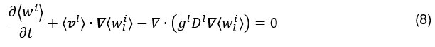
Fluid mechanics is described by the Navier-Stokes equation averaged over the liquid phase within a representative elementary volume10:
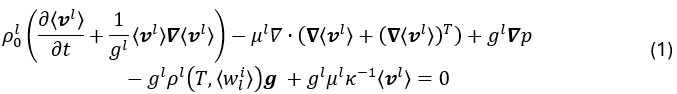
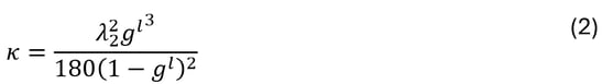
where ρ0l is the liquid density corresponding to the reference temperature Tref, ⟨v l⟩ is the average velocity field of the liquid, gl is the liquid fraction, p is the pressure field, g represents the gravity vector, ⟨wli⟩ denotes the average concentration of solute i in the liquid phase, and κ is the Carman-Kozeny-type permeability, expressed as a function of the secondary dendrite arm spacing λ2:
The liquid density ρ0l is assumed to be constant, except in the gravity term where the Boussinesq approximation is used. This approximation now takes into account the contribution of each chemical species in the multi-component alloy:
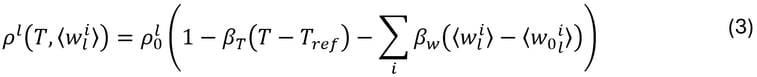
where βT and βw are the thermal and solutal expansion coefficients, respectively, while ⟨w0li⟩ and ⟨wli⟩ represent the nominal and average concentrations of solute i in the liquid phase, respectively.
The liquid is assumed to be incompressible, and the mass conservation equation simplifies as follows:
Heat transfer during solidification is modeled by the energy conservation equation:
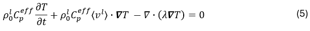
where λ is the thermal conductivity and Cpeff is the effective heat capacity, which includes the contribution of the latent heat L according to Ahmad et al.13
In a multi-component system, the computation of Cpeff becomes more complex because thermodynamic equilibrium at the solid/liquid interface depends on several alloying elements, each of which influences the liquidus and solidus temperatures differently. The relationship gs(T), which estimates the solid fraction as a function of temperature according to the Brody-Flemings microsegregation model14 with a linear approximation of phase diagrams, can no longer be explicitly defined because the temperature depends not only on gs but also on the local concentrations of each solute. Therefore, the equilibrium is solved numerically for each given solid fraction, resulting in the following implicit relation T(gs):
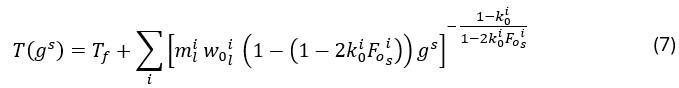
where mli represents the slope of the liquidus line for element i in the alloy, k0i is the partition coefficient of element i, FOsi is the Fourier number that characterizes the diffusivity of solute i in the solid, and Tf represents the melting temperature of the pure element. This relation is constrained by the solidus temperature Tsol, according to the formulation of Vannier15, which blocks the solidification front. The original formulation is thus inverted, by calculating the partial derivative of T(gs) with respect to gs. Consequently, Cpeff is determined as follows:
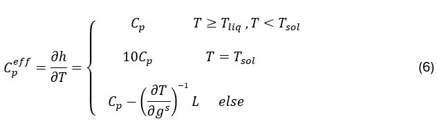
where Tliq is the liquidus temperature. This approach allows for a better account of latent heat effects and improves the prediction of the liquid and solid fractions.
Finally, solute transport for each solute i is governed by the following equation:
in which the diffusion of chemical species is considered negligible compared to convective transport and concerns only the liquid phase. The Voller-Prakash variable separation method10 is then used to first calculate the unknown ⟨wi⟩, and subsequently deduce ⟨wli⟩.
Validation of the model for a multi-binary alloy case
To validate the improvements made in the heat capacity calculation, we based our approach on the doctoral thesis work of Liu7, and applied it to a multi-component alloy. This approach allows us to compare our results with those obtained using two well-established reference codes in the literature: the SOLID16 code, based on a finite volume method, and the R2SOL17 code, developed for two-dimensional finite element simulation.
Liu’s test case simulates the solidification of the multi-binary alloy Fe – 0.2 wt% C within a square cavity measuring 100 mm on each side, as shown in Figure 2. The cavity walls are assumed to be adiabatic, except for the lateral surfaces, which are subjected to heat flux described by Fourier’s law. A zero liquid velocity is imposed along all the cavity walls.
 Figure 2: Schematic representation of the geometry and boundary conditions applied in the simulation of multi-binary alloy solidification, based on the test case proposed by Liu.
A « non-coupling » strategy is adopted in simulations performed using SOLID and R2SOL, where the system is considered locally closed, without enrichment of the liquid bath, and diffusive terms are neglected. This non-coupling strategy consists of solving, at each time step, sequentially and without strong iteration, the conservation equations for energy, solute, and momentum. In our case, the simulation was performed with coupling, using the THERCAST® model enhanced by an analytical calculation of the heat capacity and its dependence on the chemical composition.
The results of the relative segregation of the carbon mass concentration, defined as  , are shown in Figure 3, in comparison with literature results. The carbon distribution predicted by THERCAST® shows good agreement with the results from SOLID and R2SOL. In fact, positive segregation is observed in the upper part and negative segregation in the lower part, which is a consequence of the upward movement of carbon-enriched liquid in the mushy zone. Moreover, the THERCAST® results reveal finer segregation structures (Figure 3(c)) in comparison with the reference results. Furthermore, adopting an iterative coupling strategy, such as that proposed by Bellet et al.18, further improves accuracy, especially regarding the minimum and maximum carbon concentrations, at the expense of increased computational cost.
 Figure 3: Maps of carbon mass concentration simulated according to the lever rule after 10 minutes of solidification of the multi-binary alloy Fe–0.2% C, using (a) SOLID®, and (b) R2SOL®, compared with (c) the result from the enhanced THERCAST® model for coarse (left) and fine (right) meshes.
To adjust the level of thermodynamic fidelity according to the available computational resources and the desired accuracy, an approach relies on reactivating enrichment types (0 and 1) beyond the simplified type 2 scheme, in order to better represent the local enrichment of the liquid bath. Within this framework, the solidification path is imposed locally for each representative elementary volume (REV) according to one of the following approaches:
- Type 2 enrichment: the solidification path is fixed by the initial nominal concentration, assuming a fully liquid initial state. Neither the enrichment of the liquid nor that of the mushy zone is taken into account. This scheme corresponds to the non-coupling strategy of R2SOL, where the solidification path is predefined and remains unchanged throughout the simulation.
- Type 1 enrichment: the path is defined from the last liquid concentration before the start of solidification in each REV. Only the enrichment of the liquid bath is considered, with the path fixed from the beginning of the local solidification.
- Type 0 enrichment: the solidification path is continuously updated based on the instantaneous local concentration. Both the enrichment of the liquid and the mushy zone are considered, and the path evolves dynamically throughout solidification.
Figure 4 below shows the distribution of manganese segregation in the solid state for three distinct configurations. With conventional type 2 enrichment and a constant heat capacity, Figure 4(a) displays a coarse representation of macrosegregation. The use of an analytical calculation of Cpeff, while maintaining type 2 enrichment, reveals more detailed features, with more pronounced regions of positive and negative segregation (Figure 4(b)). Finally, the combined use of type 0 enrichment and the analytical calculation of Cpeff results in a slightly more refined distribution of manganese segregation in certain regions of the ingot (Figure 4(c)).
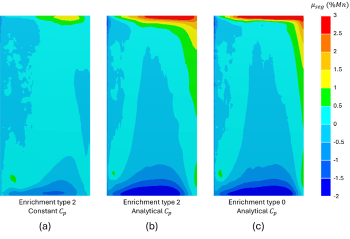
Figure 4: Relative manganese segregation maps after 1000 s of solidification, simulated under three different configurations: (a) type 2 enrichment with a constant Cp, (b) type 2 enrichment with analytically evaluated Cp, and (c) type 0 enrichment with analytically evaluated Cp.
Conclusion
This article demonstrates the ability of the THERCAST® model to accurately predict macrosegregation in multi-component alloys, while allowing the user to adjust the level of detail according to computational time constraints.
The improvement in heat capacity calculations and the extension of options for enriching the solidification path enhance thermodynamic consistency and the reliability of predictions. These advancements ensure behavioral continuity between binary reference cases and more realistic multi-binary scenarios. With these developments, THERCAST® provides industrials with a robust, accurate, and flexible simulation tool to better control the quality of solidified products.
Stay tuned for our upcoming publications, which will present further enhancements to the model, notably including the consideration of equiaxed grain sedimentation.
References
1. Yan, G., Han, L., Li, C., Luo, X. & Gu, J. Effect of macrosegregation on the microstructure and mechanical properties of a pressure-vessel steel. Metallurgical and Materials Transactions A 48, 3470–3481 (2017).
2. Pickering, E. & Bhadeshia, H. Macrosegregation and microstructural evolution in a pressure-vessel steel. Metallurgical and Materials Transactions A 45, 2983–2997 (2014).
3. Rivaux, B. Simulation 3D éléments finis des macroségrégations en peau induites par déformations thermomécaniques lors de la solidification d’alliages métalliques. (2011).
4. Campbell, J. Castings. (Elsevier, 2003).
5. Ludwig, A., Wu, M. & Kharicha, A. On macrosegregation. Metallurgical and Materials Transactions A 46, 4854–4867 (2015).
6. Gouttebroze, S. Modélisation 3D par éléments finis de la macroségrégation lors de la solidification d’alliages binaires. (2005).
7. Liu, W. Modélisation par éléments finis des phénomènes thermomécaniques et de macroségrégation dans les procédés de solidification. Thèse de doctorat, Ecole Nationale Supérieure des Mines de Paris (2005).
8. Carozzani, T. Développement d’un modèle 3D Automate Cellulaire-Éléments Finis (CAFE) parallèle pour la prédiction de structures de grains lors de la solidification d’alliages métalliques. (2012).
9. Nguyen, T.-T.-M. Multiscale finite element modeling of macrosegregation and grain transport. Thèse de doctorat, Ecole Nationale Supérieure des Mines de Paris (2015).
10. Saad, A. Modélisation par level set des macroségrégations induites par le retrait à la solidification. (2016).
11. Ettroudi, H. Modélisation numérique multi-échelle des structures de solidification, de la macroségrégation et de la Transition Colonnaire-Equiaxe. Thèse de doctorat, Ecole Nationale Supérieure des Mines de Paris (2021).
12. Hebditch, D. J. & Hunt, J. D. Observations of ingot macrosegregation on model systems. Metallurgical transactions 5, 1557–1564 (1974).
13. Ahmad, N. et al. Numerical simulation of macrosegregation: a comparison between finite volume method and finite element method predictions and a confrontation with experiments. Metallurgical and Materials Transactions A 29, 617–630 (1998).
14. Rappaz, M. & Dantzig, J. A. Solidification. (EPFL Press, 2009).
15. Vannier, I., Combeau, H. & Lesoult, G. Numerical model for prediction of the final segregation pattern of bearing steel ingots. Materials Science and Engineering: A 173, 317–321 (1993).
16. Vannier, I. Modélisation de la solidification des lingots d’acier. Thèse de doctorat, Institut National Polytechnique de Lorraine (1995).
17. Gaston, L. Résolution numérique par éléments finis d’un modèle de solidification pour alliages métalliques multiconstitués. CEMEF internal report (1999).
18. Bellet, M., Fachinotti, V., Gouttebroze, S., Liu, W. & Combeau, H. A 3D-fem model solving thermomechanics and macrosegregation in binary alloys solidification. Symposium on Solidification Processes and Microstructures, in Honor of Wilfried Kurz, TMS Annual Meeting 41–46 (2004).