
A good solution for the forging industry to reduce production costs and improve productivity is to increase die life. It is estimated that nearly 10% of the final forged product’s value is linked to die spending. Anticipating defects on dies caused by wear, thermo-mechanical fatigue and plastic deformation is therefore crucial to increasing tool life.
Why use simulation?
FEM simulation software such as FORGE® and COLDFORM® are used to predict these mechanisms with accuracy that is close to reality. Thanks to die analysis, the user may then perform preventive maintenance or optimize tool geometry to obtain a larger number of forged pieces per tool set.
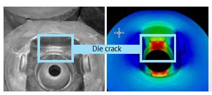
Crack on a forging die. Real part vs. FORGE® simulation
The advanced capabilities of these software packages are used to analyze the die’s behavior during hot or cold forming processes. The benefits include:
- Identifying areas subject to excessive stress (compression, tension)
- Testing changes to geometrical parameters (fillets, etc.)
- Sizing pre-stressed tools
- Increasing tool service life

What causes die failure?
Wear is the most important cause of failure and the most commonly found culprit in hot forging processes. Abrasive wear, adhesive wear, surface fatigue and erosive wear involve superficial material loss due to mechanical actions in contact with another material.
Mechanical fatigue is also a big issue in hot forging industries and can lead to total tool breakage. It consists of progressive, localized structural damage that occurs when a material is subjected to cyclic loading. This kind of failure is more common in final forging processes, where the material has already been forged in a pre-form and has a form close to the final tools.
Another important cause of failure is thermal fatigue, which is surface cracking resulting from cyclic thermal stresses only. Sudden cooling for lubrication deposition, which is done in ambient temperature, causes the tool surface to cool very quickly and can lead to surface cracking after several forging cycles.
Finally, plastic deformation is the permanent deformation of the tool surface due to stresses higher than the yield field. It leads to products outside the specification limits and normally occurs in corners and small-volume areas.
Die analysis simulation approaches
Two approaches are available in FORGE® and COLDFORM® software to conduct your die analysis and study the stresses in the dies.
Uncoupled approach
An uncoupled analysis computes the deformation of the die a posteriori as the process was simulated based on the assumption that the dies are rigid. Die surface stresses are stored during rigid computation so they can be used afterwards for a mechanical analysis conducted strictly on the dies.
The results are not as precise as in the coupled analysis. The computing cost is much lower, however.
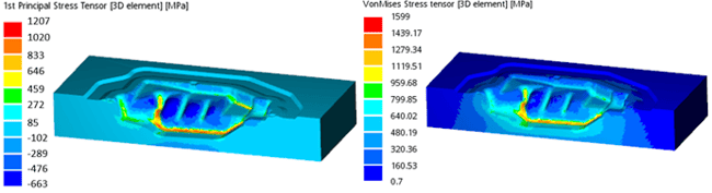
Left: The first principal stress tensor shows elements in tensile state
Right: Von Mises stress shows areas that may undergo plastic strain
Coupled approach
In coupled analyses, dies are meshed in volume and considered as deformable bodies. Each body will impact the others. Thermal and mechanical equations are solved on the billet and the dies.
This approach provides more precise results but implies that the computing cost is much higher for a coupled, part-deformable die analysis than for a classic analysis with rigid dies.
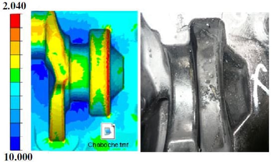
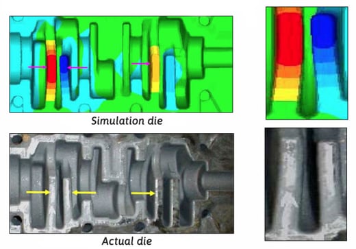 Top: Computation of tool deformation / Bottom: Experimental observation
The direction of actual horn bend matches the simulation exactly. Courtesy of Bharat Forge (India)
Virtual interference fit simulation
An interference fit, also known as a press fit or friction fit, is a form of fastening between two tight fitting parts that produces a joint held together by friction.
To model an interference fit in FORGE® or COLDFORM®, deformable dies have to be used. For an interference fit with several die cases, several deformable dies are needed. This will, however, considerably increase the computing cost.
The virtual interference fit technique reduces computing costs by replacing several deformable dies with a virtual pre-stress on one deformable die. With the virtual interference fit, there is no need to model the two deformable outer dies. A normal stress applied to the first die is computed according to the impact of the third die on the second and of the second on the first.
Thanks to the virtual interference fit, the user can:
- Avoid the modeling of all the parts, which decreases the computation time
- Avoid face discretization issues between the ring and the insert
- Consider several rings
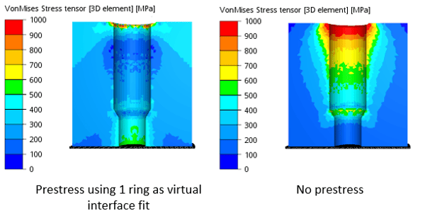
Comparison of the Von Mises results between two cases with pre-stress and without. When computing pre-stress using virtual interface fit: Von Mises stress values are lower (the die is less deformed) and the mechanical behavior of the die is improved.
Die analysis after several forging cycles
Under certain situations, various phenomena such as fatigue, damage and die wear must be estimated more precisely. Thermal phenomena are therefore very important. A calculation in the dies after one single forging cycle is not enough, because the thermal equilibrium is only reached after several cycles.
In this case, it is required to perform a steady-state analysis. The principle is to estimate the temperature gradient in the dies after stabilization.
Steady-state analysis
FORGE® considers each stage of the forging cycle: waiting time, forging operations, cooling stage and die lubrication stage.
During this cycle, the evolution of the different thermal values (effusivity, emissivity, etc.) is stored. By the end of the thermomechanical computation of a forging cycle, the thermal steady-state regime calculation begins. It will take advantage of the history of the thermal values computed on the first cycle to make a thermal calculation for each of the N following cycles until reaching thermal equilibrium.
An Archard wear model gives quantitative and accurate results. This model is a function of the lubricant, the material and the tribological parameters: the friction coefficient.
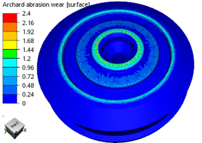
Archard wear on a lower die
Crack prediction
If we know the thermal and mechanical strains and all the material parameters, the number of forging cycles until cracking can be calculated using the following equation:
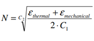
 Cycles until crack initiation
Methodology implemneted and comparison