
Introduction
Fasteners such as screws, bolts, nuts, washers, studs, or rivets are designed to operate in highly demanding environments, where even minor failure can lead to critical consequences. Behind their apparent simplicity lie complex manufacturing processes based on cold forming, such as wire drawing, multi-pass forming, and thread rolling (see Figure 1). Each of these steps directly influences the mechanical properties of the final component.
Designing a high-performance fastening component is therefore a real engineering challenge. It involves not only defining an appropriate forming sequence, but also balancing several requirements: reducing production costs, meeting geometric and weight constraints, improving mechanical performance, and preserving tool life.
In this demanding context, a major issue remains the often late detection of defects, typically identified after manufacturing, leading to significant losses in material, time, and resources. The use of the COLDFORM® simulation tool makes it possible to anticipate these difficulties from the design stage.

Figure 1: Illustration of the manufacturing stages of a fastener, from the wire coil to the heat treatment of the component.

Simulation of fastener manufacturing stages with COLDFORM®
The production of fasteners by cold forming involves a sequence of interdependent operations, each of them directly affecting the final quality of the part. COLDFORM® makes it possible to analyze this process chain in a consistent manner, as detailed below.
1.Wire preparation: phosphating and wire drawing
The process begins with the preparation of the metal wire. Phosphating aims to improve tribological conditions by reducing friction and tool wear, while promoting material flow. In COLDFORM®, these conditions can be incorporated through appropriate contact parameters (see Figure 2), enabling a realistic representation of tool–material interactions.
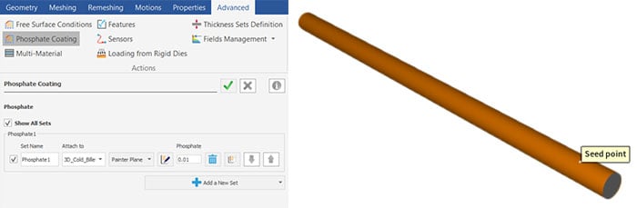
Figure 2: Phosphating functionality available in COLDFORM®.
Wire drawing then adjusts the wire diameter through plastic deformation to obtain coils with the required diameter. This operation induces strain hardening and residual stresses, whose evolution depends on the subsequent heat treatment. The wire is then typically subjected to spheroidizing annealing.
When this heat treatment is not simulated, it becomes necessary to incorporate into the simulation the effects of the plastic deformation induced by wire drawing. COLDFORM® allows the initialization of internal variable fields according to an axial or radial distribution. This feature allows to account for an initial plastic strain gradient along the radius of the billet, thereby providing a more representative modeling of the material state at the entry of the next stage of the process.
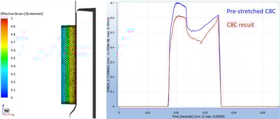
Figure 3: (a) Initialization of plastic strain. (b) Comparison of the forming load obtained when processing a pre-drawn and annealed wire.
2. Billet shearing
The wire is then sheared into billets with controlled dimensions. The quality of the sheared surface directly influences subsequent stages, particularly die filling and material flow during forming. Initial defects can thus propagate throughout the entire manufacturing route.
The modeling of shearing in COLDFORM® is based on adaptive remeshing techniques, which maintains mesh quality despite strong local deformations. The mesh is automatically updated during the computation, with refinement applied in the most highly strained regions. This approach improves simulation accuracy, particularly for estimating shearing forces, resulting geometry, and zones likely to exhibit defects.
Figure 4: Simulation of billet shearing prior to forming
3.Multi-pass forming sequence
The forming sequence is the key stage of the process. It consists of a succession of passes combining upsetting, extrusion, and progressive shaping. Its design must ensure, at each stage, a homogeneous material distribution, defect limitation, and controlled forming loads.
COLDFORM® enables the simulation of each stage and the analysis of a wide range of results. It allows evaluation of the final part geometry (Figure 5(a)), accounting for elastic springback, material flow into the die cavity, and the initiation and evolution of defects such as laps, cracks, underfill, or flow line defects. Other quantities, including internal stresses, temperature, and hardness, can also be assessed.
At the die level (Figure 5(b)), the analysis focuses in particular on abrasive wear, internal stresses, and fatigue phenomena. Regarding the press, the required forming load for each operation can also be determined.
Case study: development of a multi-stage forming sequence for a hexagonal head screw
The example illustrated in Figure 5(c) shows a forging sequence for the manufacturing of a screw, developed by the Miguel Altuna Institute (Spain). The process was broken down into five stages and modeled using COLDFORM®:
- Forward extrusion
- Head forming
- Hexagonal head reduction
- Combined head forming with backward extrusion
- Forward extrusion
The first three stages were simulated in 2D (axisymmetric part), while the last two stages were simulated in 3D.
Figure 5: Simulation results for the manufacturing of a screw developed by the Miguel Altuna Institute (Spain), illustrating: (a) the part, (b) abrasive wear on the punch, and (c) modeling of all stages in the forming sequence of the hexagonal head screw.
The evolution of mechanical and thermal fields, including plastic deformation, internal stresses, and temperature distribution, can be examined at each stage of the process to assess the feasibility of the forming sequence and identify critical regions (Figure 6).
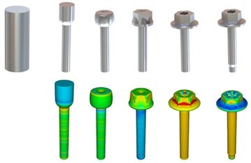
Figure 6: Forging sequence of a Torx hexagonal head screw: comparison between the experimentally obtained part and COLDFORM® simulation results (reproduced with permission from the Miguel Altuna Institute, Spain).
4. Thread rolling
Thread rolling is performed by plastic deformation between two profiled tools, inducing a favorable grain flow orientation for surface mechanical properties. However, this process is accompanied by strong stress gradients and complex kinematics.
COLDFORM® enables predictive simulation of thread formation on the screw (see Figure 7(a)). The software reproduces the actual kinematics applied by the comb or rolling dies using a contact algorithm and an appropriate time integration scheme. Volume conservation of the screw is ensured through a suitable rotational update, providing a realistic representation of the process. Internal and external stress fields are thus accurately evaluated. In addition, the use of cross-sectional views allows to anticipate and precisely locate areas of thread underfill, as shown in Figure 7(b).
 Figure 7: (a) Modeling of the evolution of equivalent stresses during the threading operation (reproduced with permission from the Miguel Altuna Institute). (b) Identification of thread underfill regions using a cross-sectional plane
5. Heat treatments
Fasteners must exhibit high strength, as they are frequently subjected to significant tensile and shear loading. The required metallurgical and mechanical properties are obtained through heat treatments such as heating, quenching, and tempering.
Following the cold forming simulation in COLDFORM®, heat treatment processes can be modeled using SIMHEAT® (see Figure 8) or FORGE®, while preserving the mechanical and microstructural history resulting from the forming process.
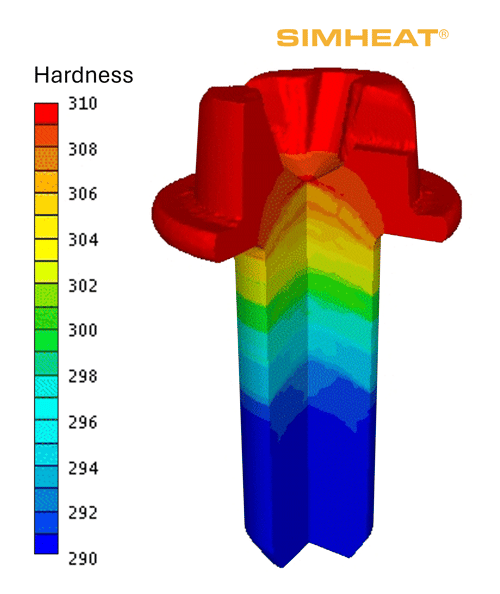
Figure 8: Hardness distribution in a screw after tempering simulated using SIMHEAT®.
Assessment of assembly robustness using COLDFORM®
COLDFORM® can also be used to model various types of mechanical assemblies, such as riveting, clinching, flow drilling screw fastening, nailing, or bolting (see Figure 9). The software enables continuous analysis of the entire chain, from component manufacturing to assembly and subsequent mechanical loading.
Results from assembly simulations, including residual stresses, can be directly transferred to mechanical loading simulations. This continuity enables the assessment of in-service performance of assemblies, particularly through static tests.
From a process perspective, this approach enables:
- Ensuring process feasibility by controlling each step of the model setup,
- Evaluating the influence of key parameters, such as geometries, coatings, or installation forces,
- Controlling dimensional tolerances and fastening properties,
- Optimizing operating conditions to reduce costs and accelerate time-to-market.
From a product perspective, this approach allows:
- Accounting for the thermo-mechanical history of the material after manufacturing,
- Testing product behavior under service conditions,
- Predicting performance and service life of fastening systems.
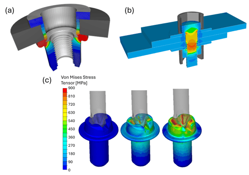
Figure 9: Modeling of assembly operations using COLDFORM®: (a) plastic strain results during crimping of a RIVKLE® rivet nut (Böllhoff), (b) von Mises stress in a bolted assembly, and (c) stress evolution during screw tightening.
The COLDFORM® solver includes features specifically suited for the simulation of complex mechanical assemblies. Multi-body contact handling is based on a robust master–slave algorithm, enabling efficient treatment of interactions between components. Self-contact is also taken into account, with control of node penetration within a single body.
Adaptive remeshing plays a key role in this type of computation. It accounts for the high sensitivity of damage criteria to mesh refinement in sheared or damaged regions. The software provides both local and global remeshing strategies, with automatic mesh adaptation based on gradients of strain, strain rate, or a damage criterion.
These capabilities support various types of analyses, such as the simulation of bolted assemblies (see Figure 10), including determination of torque and optimal tightening sequence. They also enable the study of bolt preloading, evaluation of mechanical strength through static tensile and shear tests, as well as tightening configurations within the plastic range of the screw.
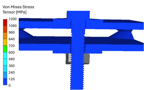
Figure 10: Evolution of the clamping force during tightening of a bolted assembly.
Key features of COLDFORM® for fasteners
COLDFORM® covers the full range of functionalities required to simulate fastener manufacturing processes, while enabling the evaluation of mechanical and metallurgical properties at each stage of the process. COLDFORM® notably provides:
- Predefined simulation templates for forming operations: wire drawing, cold forging, extrusion, thread rolling, etc.
- A comprehensive optimization module enabling automatic determination of optimal process parameters to ensure a defect-free, high-performance final product, as well as the execution of design of experiments (DOE) to identify an optimal configuration.
- A material database containing more than 250 materials characterized for cold forming applications.
- Compatibility with the JMatPro® databases, enabling modeling of most industrial materials.
- A cold rheology generation tool allowing users to create and modify their own material files.
- Springback prediction based on the last simulation increment, which evaluates displacement due to elastic recovery (see Figure 11(a)).
- Marking tools enabling visualization of fiber flow defects and tracking fiber evolution at each forging stage (see Figure 11(b)). Fiber flow can be defined both during pre-processing and post-processing.
- Several damage and failure criteria, such as Latham & Cockroft, Oyane, Rice & Tracey, or Chaboche–Lemaître.
- Multi-view windows allowing up to nine simultaneous visualizations for comparison of different results and analysis perspectives (Figure 11(c)).
- Predefined curves for generating specific plots (e.g., force versus time).
- Tool stress analysis capabilities to reduce failure risk and optimize die lifetime.
- Metallurgical analyses to assess microstructural evolution and mechanical properties.
- Interoperability with SIMHEAT® to simulate heat treatments after forming.

Figure 11: (a) Visualization of springback after forming. The blue mesh corresponds to the last forging increment, while the grey geometry represents the part after springback. (b) Evolution of fiber orientation at each cold forging stage. (c) Multi-view display applied to an extrusion case.
Conclusion
Numerical simulation now enables fastener development to be addressed through a comprehensive approach that integrates the entire manufacturing chain. COLDFORM® provides the necessary capabilities to realistically model the process and to accurately analyze material behavior and the mechanical properties of the part at each stage of transformation, including heat treatment through coupling with SIMHEAT®. This framework enables the identification of critical regions and the anticipation of manufacturing defects and tool wear throughout the process.
This approach reduces shop-floor trial-and-error iterations, improves the robustness of manufacturing routes, and accelerates the industrial development of fasteners.